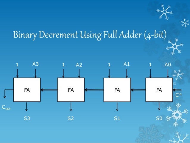
The two outputs are a Sum and Carry outputs. It consists of three inputs, of which two are input variables representing the two significant bits to be added, whereas the third input terminal is the carry from the previous addition.
Logicworks 4 increment half adder full#
As we have seen that the Half Adder cannot respond to three inputs and hence the full adder is used to add three digits at a time. Full AdderĪ Full Adder is a combinational logic circuit which performs addition on three bits and produces two outputs: a Sum and a Carry. In such applications, carry of the previous digit addition must be added along with two bits hence it is a three bit addition. We cannot add binary numbers with more than one bit as the Half Adder cannot include the ‘Carry’ information from the previous sum.ĭue to this limitation, Half Adder is practically not used in many applications, especially in multi-digit addition. Half adder is mainly used for addition of augend and addend of first order binary numbers i.e., 1-bit binary numbers.

The ‘Sum’ output is labeled as summation symbol (∑) and the Carry output is labeled with C O. In the above half adder circuit, inputs are labeled as A and B. The following image shows the Logic Diagram of a Half Adder. So, to properly implement a Half Adder, you need two Logic Gates: an XOR gate for ‘Sum’ Output and an AND gate for ‘Carry’ output.

Similarly, the values for ‘Carry’ in the above truth table resembles an AND Gate. If we observe the ‘Sum’ values in the above truth table, it resembles an Ex-OR Gate. The truth table of the Half Adder is shown in the following table.

The following image shows the block diagram of Half Adder. The inputs are the two 1-bit binary numbers (known as Augend and Addend) and the outputs are Sum and Carry. This circuit has two inputs and two outputs. Half AdderĪ logic circuit used for adding two 1-bit numbers or simply two bits is called as a Half Adder circuit. Let us take a look at the binary addition performed by various adder circuits. Depending on how they handle the output of the ‘1+1’ addition, they are divided into:

The logic circuits which are designed to perform the addition of two binary numbers are called as Binary Adder Circuits. The problem may arise when we try to add binary numbers with more than one bit. Here, the lower significant bit is called as the ‘Sum Bit’, while the higher significant bit is called as the ‘Carry Bit’.įor single bit additions, there may not be an issue. But for the fourth addition operation (where the inputs are 1 and 1), the result consists of two binary digits. In the first three operations, each binary addition gives sum as one bit, i.e., either 0 or 1. The four basic addition operations two single bit binary numbers are: If both these operations can be properly implemented, then Multiplication and Division tasks become easy (as multiplication is repeated addition and division is repeated subtraction).Ĭonsider the operation of adding two binary numbers, which is one of the fundamental tasks performed by a digital computer. Addition and Subtraction are two basic Arithmetic Operations that must be performed by any Digital Computer.


 0 kommentar(er)
